
When you look around the market, there are many different types of 3D scanners and 3D sensors out there. A quick look at PCL’s IO library lists a number of different sensors out there. Microsoft has their Kinect which use Time Of Flight to measure depth. The PR2 robot uses projected stereo mapping (i.e. It uses a projector to project a pattern onto the floor then it uses visual cues from the projected pattern to reconstruct the depth of the pattern). Then there are laser range finders which use rotating mirrors to scan depth. Some sensors use multiple camera like we use our two eyes to estimate depth. All of these methods have their own problems. Measuring time of flight is challenging and expensive, rotating mirrors with laser are slow and unsafe, stereoscopic methods are still quite inaccurate. Enter 3D Scanning Via Inverse Square Law. This is a new technique that I have hacked together using one LED and a camera. It is somewhat like projected stereo mapping but simpler and less computationally expensive.
Theory
So how does it work? In a traditional time of flight imaging system a pulse of light is sent out and the time it takes for the reflection to come back is used to gauge the distance. Light is very fast so the time difference for most objects is so minuscule that it makes the electronics very complicated. There is something else that changes with time over a distance – Power. The further we move away from a light source the less light we receive. This is characterised by the inverse square law.
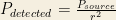
Since power is very easy to measure, in theory it should be quite easy to measure the distance from the source using this technique. The challenge arises because the brightness of the source is not constant. Not all materials reflect light in the same way. If we were to imagine a set up like the one below:
Let us assume that the light source emits light at a power of 
Then the object receives 
If its albedo is 

According to the inverse square law the light that reaches the camera is:

In most cases the 

Now we can control


These equations can be solved quite easily by using images of two different brightness. If we solve for 
Practical Implementation
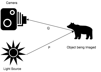
In theory this all looks very good so how do we actually implement it? My hardware looks like this: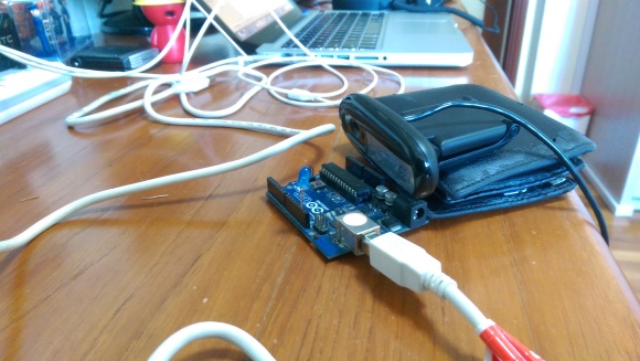
As you can see theres a blue LED, an Arduino and Logitech webcam. The arduino controls the brightness of the LED and the webcam observes. The code for the arduino is as follows:
https://create.arduino.cc/editor/arjo129/b42a42e1-00fd-499b-bd9f-c1915d9eea61/preview?embed
I know theres an analog write function but I decided to be fancy about it and do the timing myself.
The app itself is available on github: https://github.com/arjo129/LightModulated3DScan
It is written in C++ using the Qt framework and OpenCV (I’ve hard coded the path to opencv, you’ll need to change it). Theres still a lot of work to be done to get it into production quality.
Here is my first scan:


You can see the object has been digitised quite well.
Here is another scan of my mom’s glasses and a tissue box in the backdrop. The actual scan was done in broad daylight.
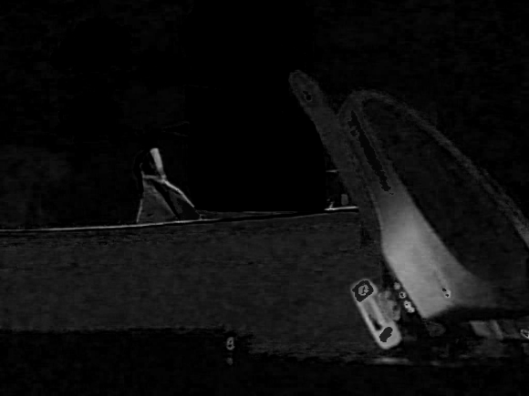
The code isn’t perfect. It currently uses unsigned chars to deal with the computation. This leads to the problem of saturation. You can see this problem on the hinge of the glasses because of the proximity of the glasses. Another image which makes this problem even clearer is this one:
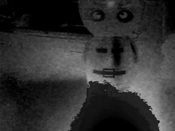
Here you can see that the parts nearest the light source and with the highest albedo are over saturated. This problem would be solved if I transitioned the code to floating point arithmetic as opposed to unsigned 8 byte integers.
